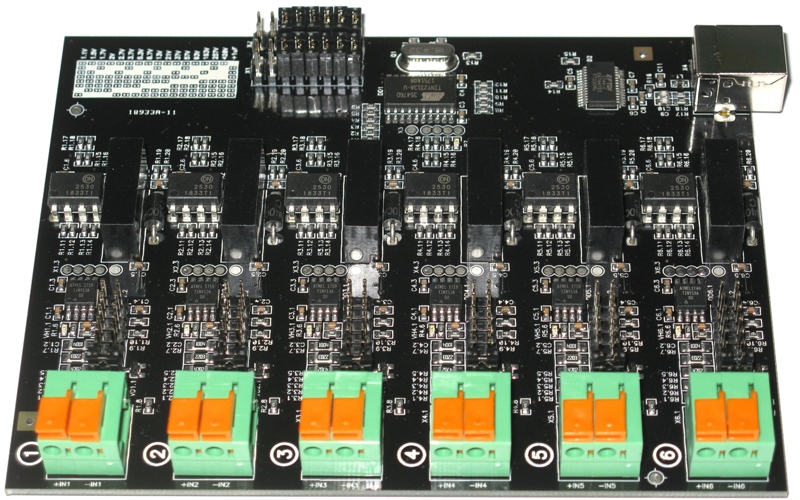
Multichannel USB data logger MRD420.6G is designed for recording unipolar signals (voltages) with a frequency of change not more than 100 Hz.
The key advantage of the device is the presence of galvanic isolation between all channels of the recorder, as well as the USB port.
Galvanic isolation allows the detection of small voltages with a large potential difference between them. For example, register the voltages on individual battery cells connected in series to a high-voltage battery.
Page content
- General information about USB data logger MRD420.6G
- What can be measured using the MRD420.6G recorder
- Main parameters of registrators MRD420.6G
- Recalculation of measurement results and calibration tables
- Measurement result files
- Software
- Ordering data loggers MRD420.6G
General information about USB data logger MRD420.6G
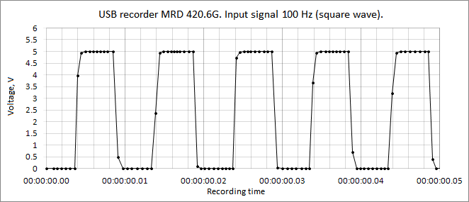
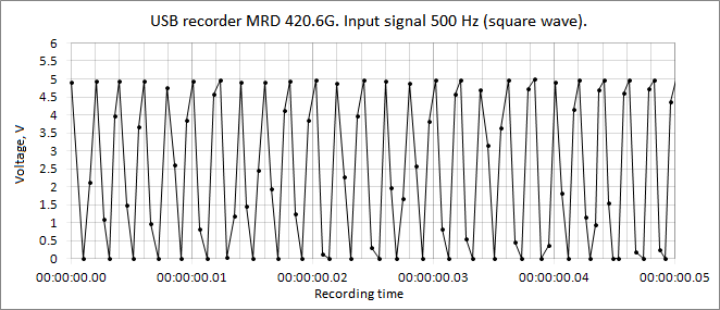
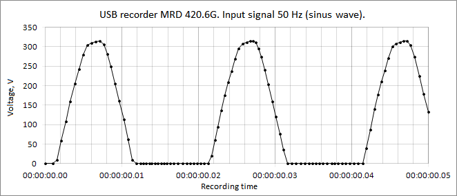
The devices are designed to register unipolar signals (input voltages) with a frequency of change not exceeding 100 Hz. The maximum sampling rate of the input voltages is about 2 kHz.
USB data logger MRD420.6G has 6 separate measuring channels.
Each channel has an independent, reconfigurable manually input voltage divider.
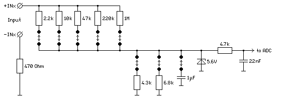
The input divider allows you to reconfigure the range of measured voltages from 0…+1.1 to 0…+420 V. The setting is made individually for each channel of the device, independently of other channels.
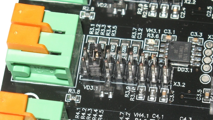
The division factor is reconfigured by setting the jumpers to the required positions, according to the table on the recorder board.
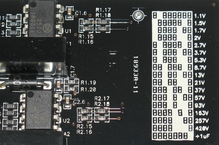
| Division ratio | Measured voltage range, V | Division value, V |
| 1 : 1 | 0 … +1.1 | 0.0011 |
| 1 : 1.32 | 0 … +1.5 | 0.0014 |
| 1 : 1.51 | 0 … +1.7 | 0.0016 |
| 1 : 1.84 | 0 … +2 | 0.002 |
| 1 : 2.5 | 0 … +2.7 | 0.0027 |
| 1 : 3.3 | 0 … +3.7 | 0.0036 |
| 1 : 4.8 | 0 … +5.3 | 0.0052 |
| 1 : 7.9 | 0 … +8.7 | 0.0085 |
| 1 : 12 | 0 … +13 | 0.013 |
| 1 : 19 | 0 … +21 | 0.02 |
| 1 : 33 | 0 … +37 | 0.036 |
| 1 : 52 | 0 … +57 | 0.056 |
| 1 : 85 | 0 … +93 | 0.091 |
| 1 : 148 | 0 … +163 | 0.16 |
| 1 : 234 | 0 … +257 | 0.25 |
| 1 : 381 | 0 … +420 | 0.41 |
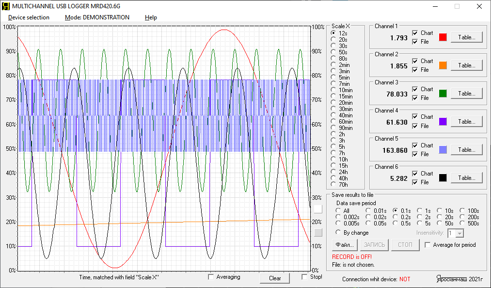
Multichannel USB data logger MRD420.6G works in conjunction with a computer.
The analog values of the input voltages are converted into numerical representations (numerical values) and transmitted to the computer. The obtained results of analog-to-digital conversion (ADC) are displayed on graphs on the computer screen.
What can be measured using the MRD420.6G recorder
USB data loggers MRD420.6G are designed to measure and record input voltages.
Nevertheless, in addition to voltage, the USB data logger MRD420.6G can measure many electrical and physical parameters, for example:
- current
- temperature
- flow rate
- presure
- force
- rotational speed
- as well as many other electrical and non-electrical parameters.
For this, various sensors and converters can be connected to the device, for example:
- current shunts (for current measurement)
- temperature sensors (for measuring temperature)
- gas, liquid flow transducers (for flow measurement)
- pressure sensors (for recording pressure)
- force sensors (for measuring force, mass)
- rotational speed sensors (for measuring the rotational speed)
- as well as many other sensors and transducers with a voltage or current output of 0-20 or 4-20 mA.
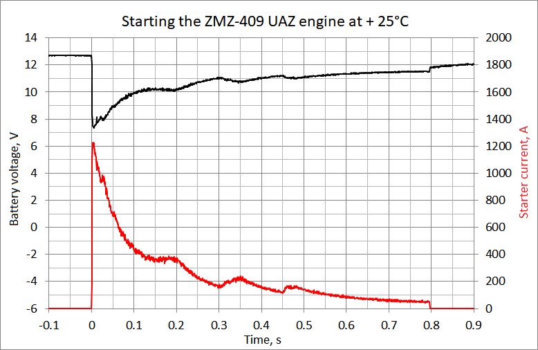
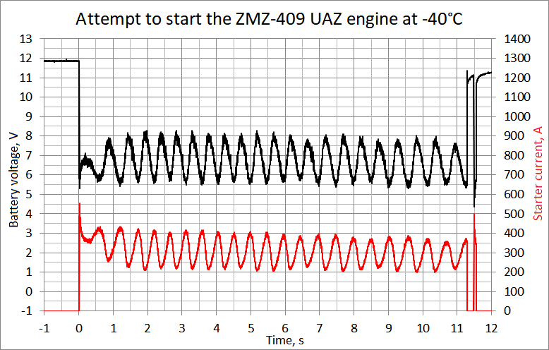
For example, the MRD420.6G USB data logger can be used to obtain the charg discharge characteristics of batteries.
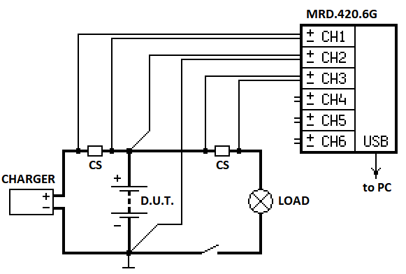
This circuit allows you to measure and record the battery charge current provided by the charger. The battery discharge current provided by the load is also recorded. In addition, the change in voltage at the battery terminals is recorded.
As a result of the subsequent processing of the measurement results, it is possible to obtain data such as:
- battery charging characteristic provided by a specific charger
- discharge characteristic of the battery (dependence of the voltage on the battery vs the returned charge)
- real battery capacity
- as well as other parameters and characteristics of charger and battery.
Below is the result of recording the voltage on the battery and the starter current when starting the ZMZ-409 engine of the UAZ car. The measurements were carried out using the MRD420.6G data logger, as well as a 200A/75mV current shunt in the starter circuit.
Main parameters of data loggers MRD420.6G
| Characteristic | Value |
| Number of independent channels | 6 |
| Input voltage range (configurable independently for each channel) | from 0…+1.1 V to 0…+420 V |
| Input voltage frequency range | from 0 to 100 Hz |
| ADC resolution of each channel | 10 bits (1024 “divisions”) |
| Maximum sampling rate | about 2 kHz for each channel |
| Electrical strength of galvanic isolation of channels | not less than 420 V |
| Computer interface | USB |
| Supply voltage | 5 V ± 10 %, via USB port |
| Power consumption | no more than 2.5 W |
| Dimensions | 130 x 100 x 18 mm |
| Weight without packaging | 0.12 kg (0.26 lbs) |
Recalculation of mesurement results and calibration tables
USB data loggers MRD420.6G return the results of converting the input voltage in the form of real numbers. Return values range from 0.0 to 1023.0.
Zero value corresponds to zero input voltage.
The value 1023.0 corresponds to the maximum input voltage for a specific setting of the voltage divider on this channel of the device.
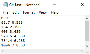
To obtain measurement results in reasonable units (e.g. Volts or Amperes), you should prepare a calibration table for each channel.
The calibration table contains two columns.
The first column is the ADC result values returned by the recorder (from 0.0 to 1023.0).
The second column is the actual values of the measured parameter (for example, in Amperes) corresponding to these ADC results.
The calibration table is prepared and set by the User individually for each channel. The preparation of the calibration table is carried out during the presetting of the device, taking into account:
- the selected division ratio of the input voltage divider
- type, value, as well as units of the measured parameter
- the type and rating of the sensor used (e.g. current shunt)
- as well as the transfer characteristic of the sensor used (for example, linear, logarithmic, parabolic, or any other).
Measurement results files
As a result of the operation of the MRD420.6G USB data logger, the User receives:
- graphs of measured parameters with values on a vertical scale from 0 to 100%, updated in real time
- numerical instantaneous values of the measured parameters displayed on the computer screen and updated in real time
- measurement results files
The files of measurement results are the most important result of the work of the MRD420.6G recorders.
According to the measurement results files, the User can:
- build graphs of parameter changes in any form with the required detail
- calculate secondary parameters (for example, power, which is the product of voltage and current)
- calculate integral parameters (for example, the capacity of the tested battery)
- and also carry out any further processing and found any necessary values.
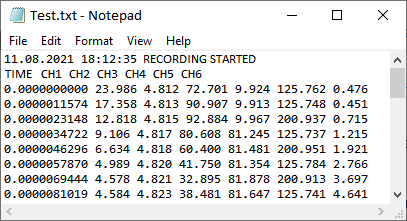
The measurement results file consists of:
- the initial record, which fixes the date and time of the beginning of the recording of the results to the file
- string with header data columns
- column of time elapsed from the start of recording the result file (time is expressed in days)
- columns of measurement results for all selected device channels
- as well as the end record, which fixes the date at the time of the end of recording the results to the file.
Columns in the measurement file are separated from each other by spaces.
Measurement data files can be opened in various programs for further processing. For example, in Microsoft Excel.
Software
Multichannel USB data logger MRD420.6G is supplied with specialized software. The software is installed on the User’s computer and allows:
- receive ADC results performed by the MRD420.6G recorder
- display the received data on graphs in relative units (from 0 to 100% of the selected input voltage range)
- recalculate the ADC results in accordance with the specified calibration tables, for example, in Volts or Amperes
- display measurement results on a computer screen
- and also save the obtained data to files of measurement results with a specified sampling step of parameters in time.
Ordering USB data loggers MRD420.6G
To order USB data loggers MRD420.6G send a request to the email address Yarstst@gmail.com
We supply USB loggers under a supply contract.
The cost, as well as the delivery time, depends on the required number of devices.